
Monitoring voltage and amperage trends during routine checks is a simple yet effective practice for maintaining plating line efficiency and quality.
Drew Adkins, Technical Service and Laboratory Manager, A Brite Co.
Introduction
An understanding of the basic electronic principles and the role they play within an electroplating solution can be a valuable skill for both the novice and experienced plating professional. This article may be used as a brief primer on the electronic forces known as voltage, amperage, resistance and their connection (no pun intended) with electroplating solutions. These electronic properties govern the very nature of the electrodeposition and knowing how to optimize them for maximum plating performance will yield a high-quality finish and a relatively stress-free plating experience. It is useful to keep these fundamentals in mind while troubleshooting as well since it is often the case that changes in these forces will indicate the root cause of the issue at hand.
First, let’s define some terms.
Voltage, or Volts for short, denoted as V, describes the measure of the potential difference or electromotive force between two points in a circuit. Think of it as the “pressure” that drives the electric amperage through a circuit.
Amperage, or amps for short, denoted as I, describes the measure of electric current flowing through a circuit. Loosely analogous to water flowing through a pipe. Increasing voltage is akin to increasing pressure within a water pipe system. Likewise, increasing amperage is akin to increasing the flow of water through the pipe system.
Lastly, it’s important to define and discuss resistance, as it will be vital to our discussion later. Resistance (R) is the opposition to the flow of electric current in a conductor. High resistance yields low current flow. Think back to our water pipe analogy; if we introduce obstructions within the pipe, we introduce higher resistance to flow of water in the system.
Ohm’s Law
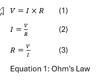
What has been described up to this point is known as Ohm’s Law and is mathematically shown below in Equation 1. Careful study of these mathematical expressions will shed more light on the nature of interaction between these concepts. For instance, in expression 2, we see that as resistance increases and voltages stay the same the amps will decrease. This can be a problem if the plating operator requires a set amps per square foot to achieve the required thickness. In this example, to maintain the correct amperage, the voltage will need to compensate by increasing to meet the need. This is valuable information and will be explored later. While one could delve deeper into this topic, this paper will focus on the practical application of these forces in plating, specifically how this knowledge can be used to troubleshoot common issues.
Application
There are a myriad of different electrochemical metallic deposition methods that we could talk about. In some cases, electrolytic reduction or electroplating is the only method available to obtain and purify active metals [1]. For simplicity, let’s describe a generic plating solution as a water-based solution containing an electrolyte. An electrolyte typically consists of salts or a mixture thereof, serving as a ‘charge carrier’ or facilitating the flow of charge through the solution. Another perspective is to view the electrolytic solution as a conductor with inherent resistance, which varies with its composition and temperature, through which current flows. This flow is directed by an electric field introduced by the rectifier through the electrodes. The Anode, connected to the positive (+) terminal on the rectifier, represents the oxidation side of the reaction, characterized by localized positivity. Oxidation is an electrochemical process in which a metal atom loses an electron, becoming a cation. This is facilitated by the electrolyte balancing the valance electronic charge of the newly formed metal complex dissolved in solution. Completing the circuit, the Cathode, connected to the negative (-) terminal, facilitates the reduction of metal cations into a plated metal surface on the workpiece, characterized by localized negativity. Reduction is the process by which a metal ion gains an electron, reducing its charge back to zero.
The conductive anodes are often, but not always, in the metallic form of the solubilized metal electrolyte dissolved within the solution. For instance, in an acid chloride zinc plating solution, the anodes may be zinc metal, while the electrolyte comprises a mixture of zinc chloride and various other chloride salts [2].

Figure 1: A simple illustration of an electroplating cell. The workpiece is coated via reduction of the metal dissolved in solution which is also often the metal used for the anodes. The anodes replenish the dissolved metal in solution via oxidation.
A careful study of the graphic in Figure 1 we can see the flow of current[1] being from positive to negative. In the case of electroplating, a rectifier is used to generate a negative charge on the workpiece, denoted with a W and a positive charge[2] on the conducting metal anode. Let’s delve through what is happening. Electrochemical reactions must remain balanced in charge, therefore the electrons required to reduce the metal ions into plated metal on the workpiece are pulled from the metal anode, M. By pulling electrons from the metal anode, it is often dissolved into the solution producing more ionized metal ions, denoted as M+, which in turn, supplies the electrolytic solution with more metal ions to be plated out of the solution.[3] However, these positively charged metal cations are not free radicals, rather they are stabilized by the electrolyte, often forming a type of complex, maintaining a balanced valance electron charge. This cycle repeats during the entire plating process. The electrolyte, E+/- in a plating solution is an ionically conductive solution that facilitates the dissolution of the anodes to provide a source of metal ions for deposition. It ensures efficient current flow and maintains the electrochemical equilibrium required for consistent plating. Key components include supporting electrolytes, such as sulfates or chlorides, which enhance conductivity, and pH buffers to stabilize the bath chemistry. Electrolytes play a critical role in electroplating by conducting current and supplying metal ions. Variations in electrolyte composition, such as insufficient metal ion concentration or imbalanced pH, can lead to plating defects like uneven deposition, burning, or poor adhesion. For example, in a zinc electroplating solution, the electrolyte may consist of zinc chloride, which supplies zinc ions, ammonium chloride, which is a complexing agent offering a wider brightness range within the deposition as well as pH buffering capabilities, [2] and potassium chloride, which enhances conductivity. Proper management of these components ensures uniform deposition and high-quality finishes.
Let’s digress for a moment and touch on electroplating systems utilizing non-consumable anodes, such as trivalent chrome baths with graphite anodes or alkaline zinc baths with steel anodes, the dynamics of the plating process differ significantly from systems using consumable (sacrificial) anodes. These differences arise because the anode material does not dissolve into the electrolyte to replenish metal ions. Instead, the electrolyte must be carefully managed to maintain the necessary ion concentrations and chemical balance. Since the anode does not provide a direct source of metal ions, the electrolyte must be periodically replenished with metal salts or other additives to sustain the plating process. For example: In trivalent chrome systems, periodic additions of chromium salts are necessary.[3] Likewise, in alkaline zinc systems, zinc ions must be replenished externally, often through controlled additions using a zinc generator system. [2]
Non-consumable anodes are more prone to polarization, where the buildup of reaction products (e.g., oxygen gas or hydroxide ions) on the anode surface can increase system resistance. In trivalent chrome plating, maintaining appropriate levels of chloride or fluoride ions in the bath helps mitigate polarization by promoting smoother anode reactions. [3] They are also prone to contamination and fouling. Non-consumable anodes can accumulate byproducts or impurities, leading to fouling that increases resistance and decreases plating efficiency. For example, graphite anodes can develop a resistive film of oxidation products that must be periodically cleaned or replaced. Furthermore, unlike systems with consumable anodes, where the dissolution of anode material can help maintain ion homogeneity, non-consumable systems rely entirely on bath agitation and replenishment protocols to ensure uniform distribution of ions.
To avoid further complexity let’s move on to more practical information. However, the reader should understand this explanation is very basic and much more detail can be uncovered in deeper study of the subject.
Troubleshooting
Now that we have a basic grasp of electrochemistry, let’s wrap up with some practical insights for troubleshooting plating solutions. As mentioned in the introduction, resistance is a key factor that affects the flow of current. If we imagine the plating solution as a giant resistor—resisting current flow and necessitating the use of a rectifier—we begin to understand why electrolytes are so critical for efficiency. Low resistance in plating solutions is ideal, as high resistance leads to unwanted energy loss (manifesting as heat) and poor covering and throwing power in deposits, such as zinc plating. For instance, deionized water alone is a poor conductor, but adding an electrolyte significantly improves conductivity.
Maintaining proper electrolyte concentrations within the bath is fundamental to achieving high-quality plating. However, excessive concentrations can have adverse effects, such as staining or uneven thickness distribution. When troubleshooting, the first step should be to check the bath constituents and adjust them to their target values. This eliminates the possibility of resistance issues stemming from improper electrolyte concentrations.
Electrolyte concentration, though crucial, isn’t the only factor affecting plating bath resistance. Contamination plays a substantial role in the solution’s ability to conduct electricity. Contaminants such as dirty tap- water, metallic impurities, grease, oil, dirt, or even the breakdown products of proprietary additives can cause major issues with the plating. Since some of these contaminants lack an electronic charge, they increase resistivity, hindering the plating process.[4] However, metallic contaminants may not introduce a resistivity issue, they are still undesirable as they often compete for plating and can cause unsightly appearance defects on the workpiece. Many of the different varieties of contamination can be identified via laboratory analysis. Such techniques include: Atomic Absorption (AA), Hull Cell Analysis. FT-IR, HPLC, and many others. When contamination is identified as the cause of high resistance, bath treatment and filtration are typically effective remedies to restore the solution to its operating specifications.
Another factor to consider is anode polarization, which can occur in specific plating solutions. For example, in acid copper plating, a small concentration of chloride ions (50–100 mg/L) is used to mitigate anode polarization. Chlorides improve anode dissolution, ensuring a steady supply of copper ions to the electrolyte. However, excessive chloride levels can result in over-aggressive anode corrosion, leading to high levels of sludge formation and contamination in the bath. This contamination can affect plating uniformity and increase maintenance needs. Similarly, in cyanide copper plating, sodium carbonate serves as a buffering agent to prevent polarization. However, excessive sodium carbonate levels (exceeding 90–120 g/L) can introduce high resistance, severely limiting the plating range.[5]
High resistance can also originate from areas outside the solution itself. Corroded busbars and saddles, over-plated racks, or racks with unseen cracks can all contribute to resistance issues. These mechanical or structural problems, coupled with electrolyte deficiencies, create scenarios where the overall resistance of the system is significantly elevated.
How do we know when resistance is high? One method is to use a multimeter to measure resistance directly. Or one may choose to observe the system’s voltage behavior. When plating at a constant current density (measured in amps per square foot), the voltage should stabilize naturally. In a high-resistance scenario, the voltage will climb to compensate for restricted current flow. Remember, resistance impedes current, and when current struggles to flow freely through the system, voltage (analogous to pressure) increases to deliver the required current often generating excessive heat and overall poor efficiency. Monitoring voltage trends is a straightforward yet effective way to identify high-resistance situations and take corrective action. Another approach is to simply feel or use a hand-held IR Temperature gun to monitor the busbar connections for excess heat. If a connection point is found to be heating up or hotter than other points in the busing, it is most likely an indication of high resistance. For the case of a potentially damaged plating rack, a reasonable method is to use amperage clamp meter. Checking each rack while the flight bar is plating for consistent amperage is a good way to find the source of high resistant faulty racks.
Conclusion
An increasing voltage should serve as a cautionary signal to investigate potential issues within the plating system. Contamination, whether from pre-treatment tank drag-in, excess proprietary chemistry additives, or dirt and grease, is a common culprit. Similarly, worn or damaged components, such as corroded copper busbars, saddles, or poorly maintained racks, can significantly contribute to elevated resistance. Verifying the electrolyte concentration through titration, either in-house or with the support of a chemical supplier, ensures the bath is within its specified range.
If elevated voltage persists despite addressing these factors, inspecting the rectifier may be necessary. A faulty rectifier can disrupt plating operations, leading to defects such as thin plating, poor throwing power, or inadequate coverage. Reviewing recent production output, especially over the previous 24–48 hours, may reveal quality issues caused by undetected electrical problems.
In summary, monitoring voltage and amperage trends during routine checks is a simple yet effective practice for maintaining plating line efficiency and quality. It does not need to be complicated either. Simply by using our natural senses such as touching busbars or looking at rectifier voltages can uncover a major potential problem. By identifying deviations early and systematically troubleshooting potential causes, operators can minimize downtime, prevent costly defects, and uphold customer satisfaction.
References
[1] Whitten, K. W.; Gailey, K. D. General Chemistry; Saunders College Publishing/CBS: 1989.
[2] Altmayer, F. Zinc Plating; AESF Founda- tion/NASF, Inc.: 2007.
[3] Snyder, D. L. Decorative Chromium Plating. Met. Finish. Guideb. Dir. Issue 2000, 215-222.
[4] Biddulph, C.; Marzano, M. Zinc Plating. Met. Finish. Guideb. Dir. Issue 2000, 323-333.
[5] Barasukas, R. Copper Plating. Met. Finish. Guideb. Dir. Issue 2000, 234-247.
[6] Blum, W.; Hogaboom, G. B. Principles of Elec- troplating and Electroforming; McGraw-Hill: New York, 1930.
[1] The direction the free electrons are moving.
[2] A good way to think of a positive charge is the absence of an electron – sometime referred to as a hole that would prefer to be filled by an electron.
[3] It should be noted here that not all plating solutions have anodes that are consumed in this manner. There are nuances that can be explored but are beyond the scope of this article.
[4] Recall our discussion about Ohm’s Law in the Introduction.